By Kevin Player
Achieving Optimal System Performance:
Navigating the Intricacies of HVAC Sequences
As a commissioning engineer, I've faced numerous challenges ensuring the smooth operation of complex HVAC systems. In this blog post, I'd like to share an incident that underscored the intricacies of HVAC sequences for a water-source VRF system, emphasizing the necessity for a comprehensive understanding to achieve optimal performance. This story revolves around a boiler technician's well-intentioned adjustments, their unintended consequences, and the steps we took to rectify the situation while adhering to the high standards of the Millig Design Build CX Team.
The Challenge
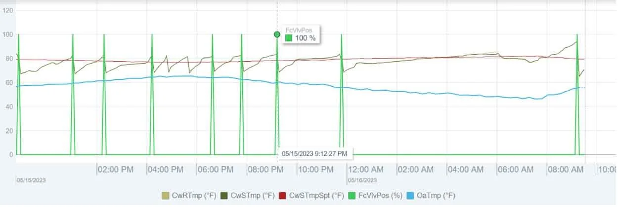
Recently, a boiler technician was called onsite to troubleshoot certain issues with our client's boilers. The technician adjusted the system, disabling the boilers when the condenser loop temperature exceeded the setpoint by 5°F, instead of the initial 2°F configuration. Although this change seemed to alleviate the immediate concerns, it inadvertently created a conflict with the Building Automation System's (BAS) determination of the condenser loop mode.
The challenge arose from the technician's lack of awareness regarding the entire system design and sequences. The technician did not realize that the new boiler disable setpoint could potentially interfere with the BAS's determination of the condenser loop mode, which was also set to 5°F on the BAS and governs the transition from switching the condenser loop from heating to cooling mode, and vice-versa. As a result, the condenser loop temperature experienced recurring fluctuations, repeatedly overshooting the 5°F threshold, triggering the opening of the fluid cooler valve, and subsequently returning to heating mode.
It is important to acknowledge that the actions taken by the boiler technician were reasonable and acceptable, especially if the recommendation was to operate the boilers with a 5°F disable setpoint. However, it is not typically within the scope of a boiler technician's role to understand the intricate sequences and programming of the condenser loop operation, which ensures optimal water temperatures for the VRF system. To address the issue and meet the standards set by the Millig Design Build CX Team, a collaborative approach was necessary.
The Solution
To rectify the situation, we engaged the Building Automation System (BAS) contractor. The resolution involved modifying the Cooling Mode to enable when the loop temperature was 10°F over the setpoint. However, this adjustment introduced the possibility of high head pressure issues with the WS-VRF heat pumps (HPs). The loop temperature needed to be maintained within a range of 70-90°F. In Heat Mode, it typically hovered around 85°F (80°F setpoint with the new 5°F offset). With the switch to Cool Mode at a 10°F offset, the maximum loop temperature would reach 90°F, potentially triggering HPs to trip off.
To ensure seamless operation and meet comfort requirements, we made additional adjustments. The loop temperature setpoints were reconfigured to enable smooth transitions when the loop needed to switch to Cool Mode due to system demand or outside air temperature. By aligning the various parameters, we hoped to enable the HVAC system to operate optimally without issues of HPs tripping off.
This incident highlights the intricate nature of HVAC sequences and emphasizes the importance of a holistic understanding when making adjustments. The resolution involved collaboration among all stakeholders, including the boiler technician, BAS contractor, and Millig's commissioning engineer, all working to uphold the high standards set by the Millig Design Build CX Team. Through careful consideration and adjustment, we successfully achieved optimal system performance, ensuring the HVAC system's smooth operation.
Fluid cooler valve (Green) opening whenever CW supply temp (Dark Green) exceeds CW loop setpoint (Red) by 5F cool mode offset indicating fluid cooler loop enabled for heat rejection. Then, as the fluid cooler rejects heat from the CW loop, the CW supply temp quickly drops 5F below the 5F CW loop heat mode offset, which then disables the fluid cooler and enables the boiler to heat the CW loop back up to setpoint.
About Kevin Player
Kevin Player is a dynamic leader and the driving force behind the commissioning and Measurement & Verification (M&V) programs at Millig Design Build. As the Director of Project Performance, he spearheads these initiatives on a national scale, ensuring optimal project outcomes across the organization. With an impressive 15-year track record in testing, verifying, and troubleshooting electronic and HVAC systems, Kevin possesses a deep understanding of the intricacies involved in achieving peak performance and energy efficiency.
OUR SOLUTIONS
Heating, ventilation, and air conditioning
Smart meters and building controls
On-site solar and other renewable energy systems
LED lighting retrofits
Building envelope improvements
Water systems
CHP-Cogeneration
And more
CONTACT US


